
I often work with CAD data that is often in paper space (not in geographic space that has real world coordinates), so I need to georeference the CAD file and be able to bring it into GIS and view it along with other GIS layers. Over the last few years, ESRI/ArcGIS has been advancing data interoperability between CAD and GIS – using ArcGIS, I love the ease with which I can pull in CAD data in GIS and vice versa for the Engineers and Architects I work with who need to pull in GIS data into their CAD software. It makes my workflow more efficient, and I can get things done faster.
I know not everyone has access to ArcGIS and/or CAD software. So for those who don’t have access to ArcGIS, here’s an alternative for working with CAD (dwg/dxf files) using QGIS. This posting goes over the workflow I use for working with CAD data in QGIS, specifically how to georeference a DXF file. Below is a quick summary of the workflow:
Install QGIS Plugins: Coordinate Capture and Another DXF Importer
Generate GCPs by: setting up 2 QGIS projects and using Coordinate Capture to get ungeoreferenced and georeferenced XY coordinates for the GCPs
Create world (*.wld) file using the GCPs coordinates
Georeference DXF using: Another DXF Importer with the wld file or ogr2ogr via the QGIS Processing Toolbox (GDAL >> Vector conversion >> Convert format)
Notes and Tips
First, some useful notes and tips that are good to know.
I’m using QGIS 3.24.2 but other 3.x versions may also work.
QGIS can read most DXF and DWG version 2000 and below (e.g. DWG R2000 or ACAD1015). But if you have a DWG file that QGIS cannot read then you may have to downgrade for convert. I use the free Windows desktop app AutoCAD TrueView Viewer.
If you have a DXF file that is already in geographic space (i.e. has real world coordinates) then you can just specify what that CRS is in QGIS and it should be correctly placed. This is just explicitly telling the software what the CRS of the DXF is. Only use the Import/ DWG/DXF tool in QIGS (Project menu >> Import/Export >> Import Layers from DWG/DXF) to convert to a geopackage when the DXF is in real world coordinates and you know what the CRS is.
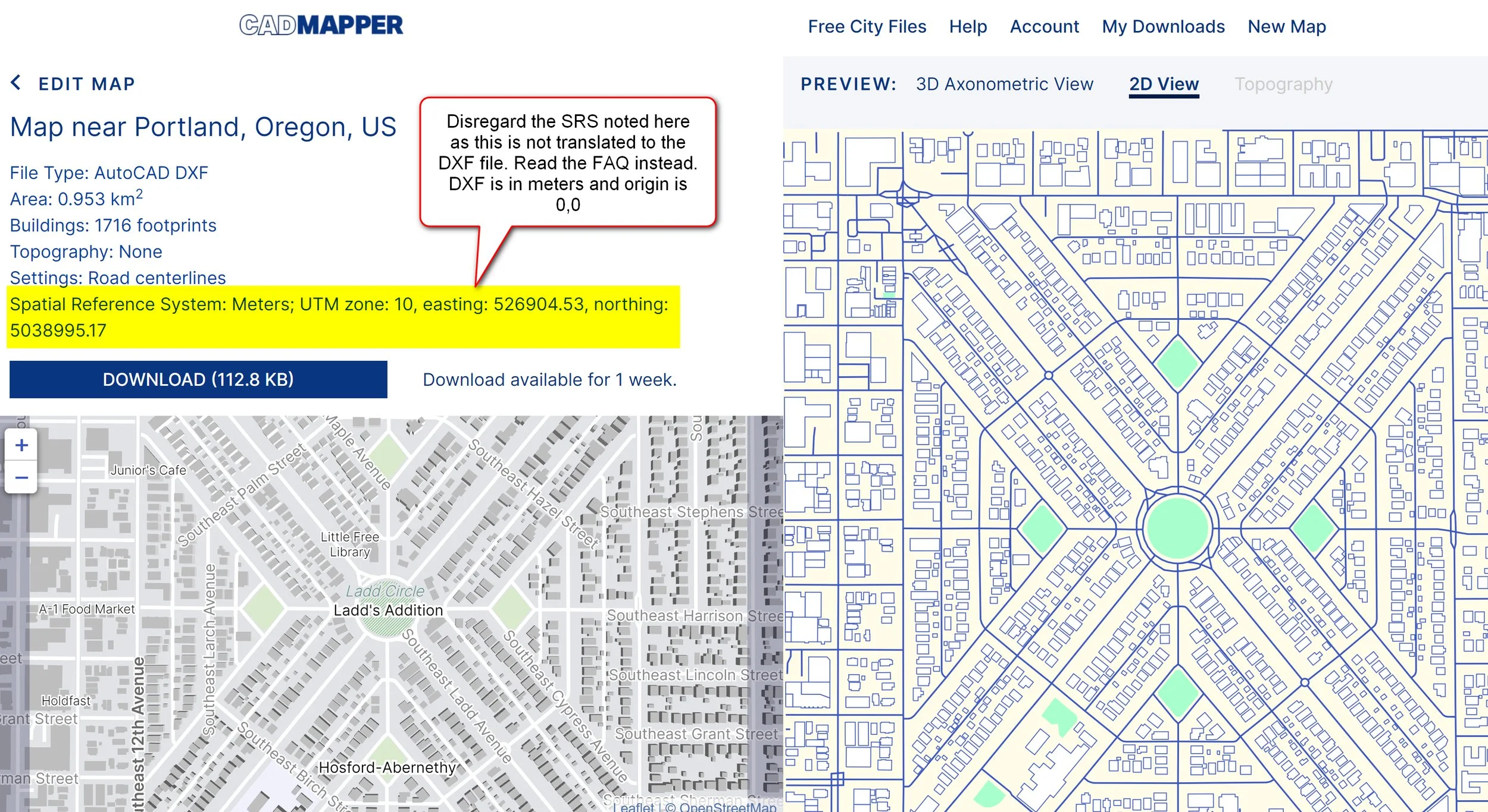
The demo DXF file used here was downloaded from CAD Mapper website. You can use this site to download publicly available data such as OSM and USGS as DXF files - free for areas up to 1 km2. If you’re using this site, disregard the CRS/SRS that’s noted in the download section - see example snapshot below, which shows a small sample area of Ladd’s Addition neighborhood in Portland.
Install QGIS Plugins
The following 2 QGIS plugins should be installed. To install plugins, in QGIS: go to Plugins menu >> Manage and Install Plugins. Search for the plugins and install it.
Install Coordinate Capture - this plugin allows you to capture XY coordinates in different CRS and is useful for getting the coordinates for GCPs used in the georeferencing.
Install Another DXF Importer - this plugin will allow you to import DXF files as well as georeference using a world (*.wld) file.
Generate Ground Control Points (GCPs)
To georeference the DXF file you will need to generate some GCPs. These will be used to link the points in the DXF file to some real world locations. So, what you do is open up 2 QGIS projects: one with just the DXF file and the other with a basemap or some other layer that has the CRS that you want to georeference the DXF to. With the two QGIS projects open, use the Coordinate Capture tool to get the XY coordinates of the GCPs.
Note: you need to do this in 2 different QGIS projects or views since the DXF has an unknown CRS. If you try to capture the coordinates in a single QGIS project/view then you won’t get the right coordinates to do the translation.
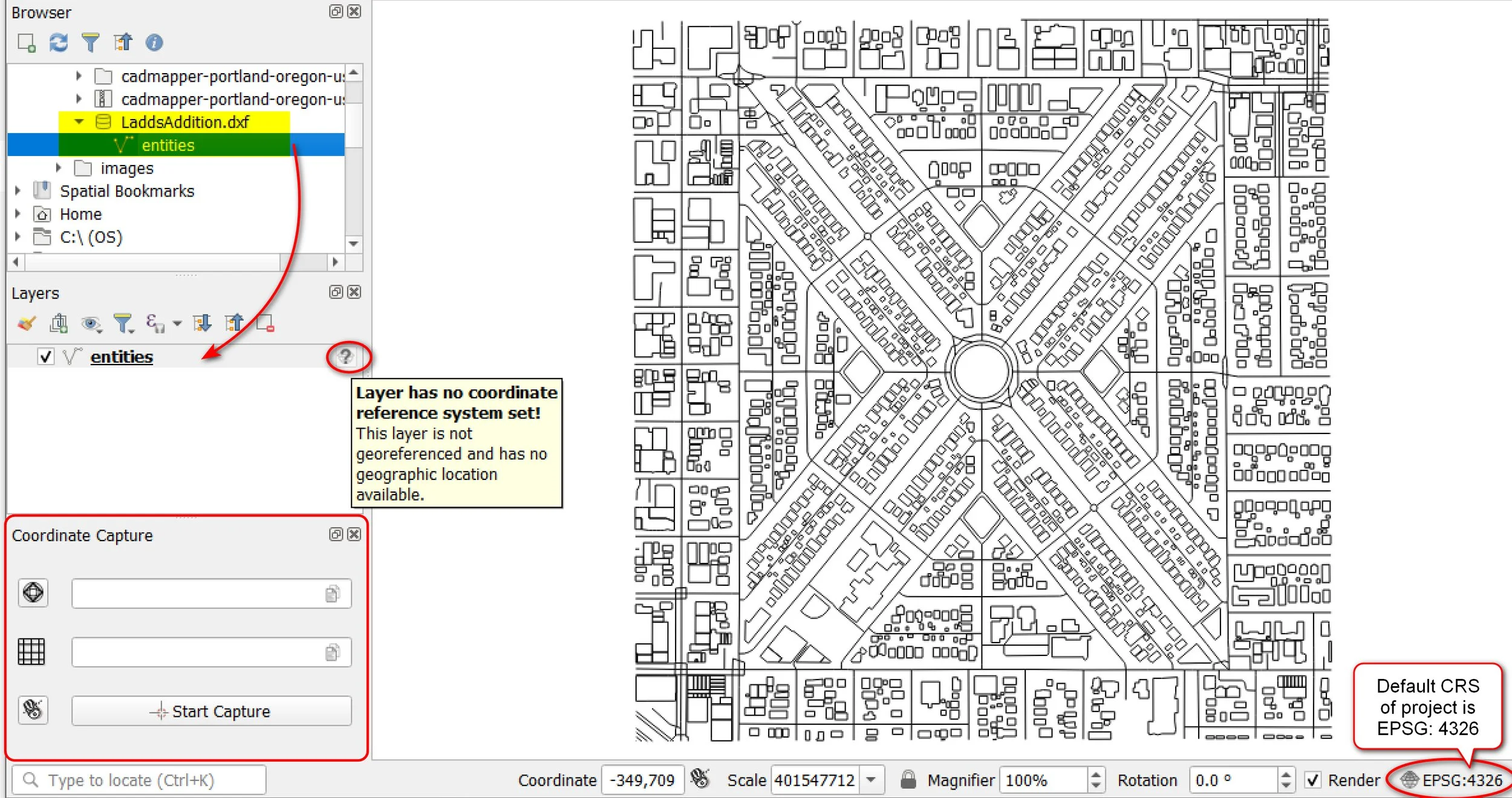
Here is my QGIS project with the DXF file that has no CRS (default project CRS will be EPSG 4326, OK to leave as is).
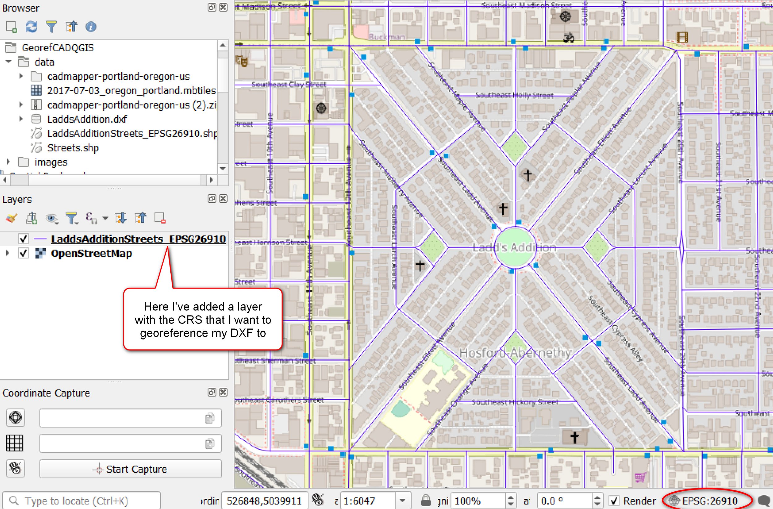
Here is my second QGIS project with a Streets layer that is in the CRS (EPSG 26910) that I want to geoereference my DXF file to. It’s shown with the OSM basemap. As a general rule of thumb, if I know the unit (e.g. meters) that my DXF is in then I want to georeference it to a CRS that uses the same unit (e.g. EPSG 26910 or NAD83 UTM Zone 10N, Meters). This is what I’m doing here.
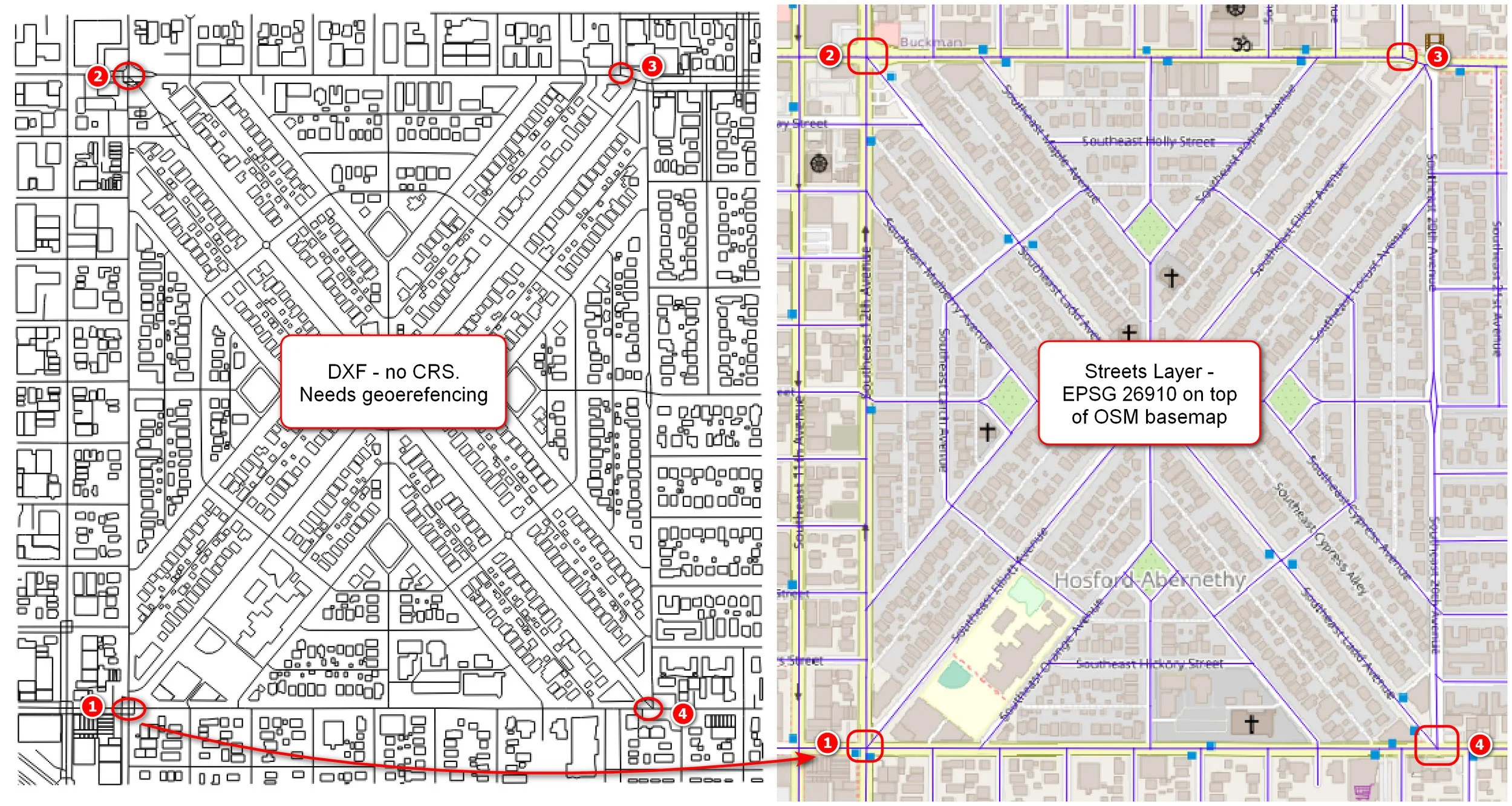
Looking at the DXF and my Streets/OSM views, I picked 4 corner points to use as my GCPs - see below. Once you find the locations you want to use as GCPs, it’s a good idea to create spatial bookmarks for them so you can easily jump to them later.
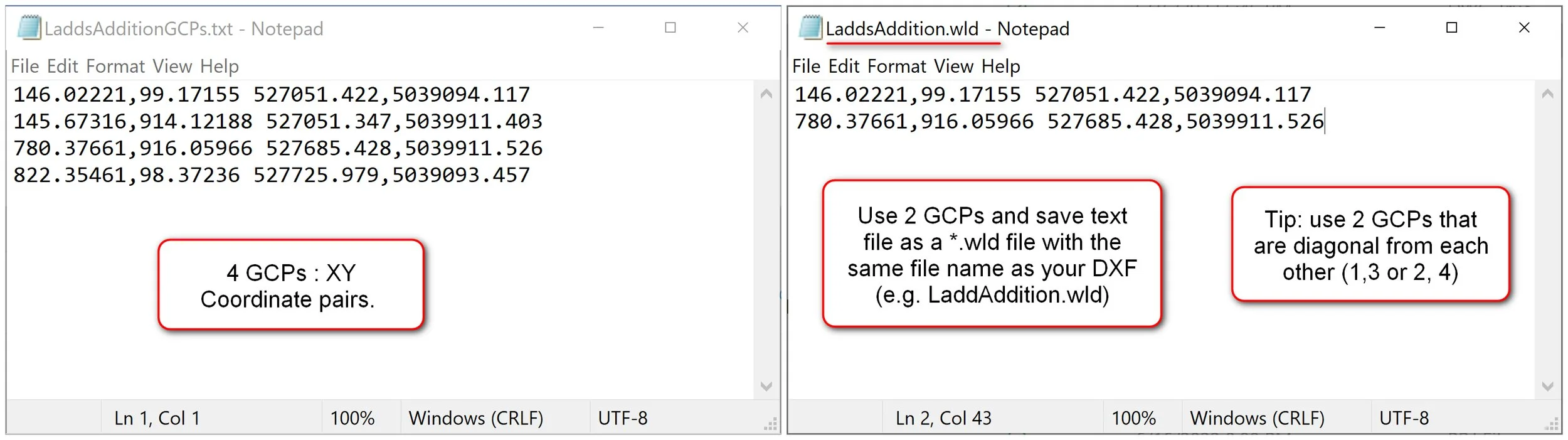
If you don’t have the Coordinate Capture panel displayed already, go to the Vector menu >> Coordinate Capture turn it on. Then going back and forth between the DXF and Streets/OSM views - use the Coordinate Capture tool to get the XY coordinates for each GCP. Copy and paste the XY coordinates for each pair of GCPs into a text file - save this text file (e.g. LaddsAdditionGCPs.txt). Continue this until you get coordinates for all 4 GCPs.
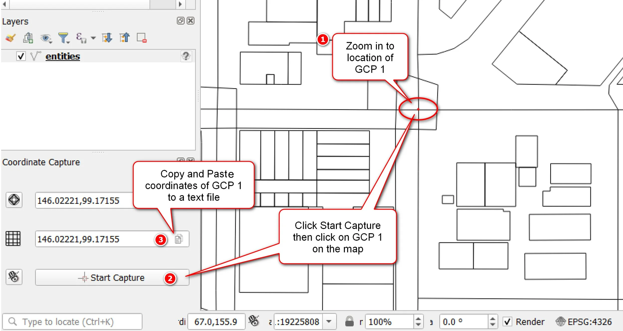
QGIS project with DXF for capturing coordinates for GCPs
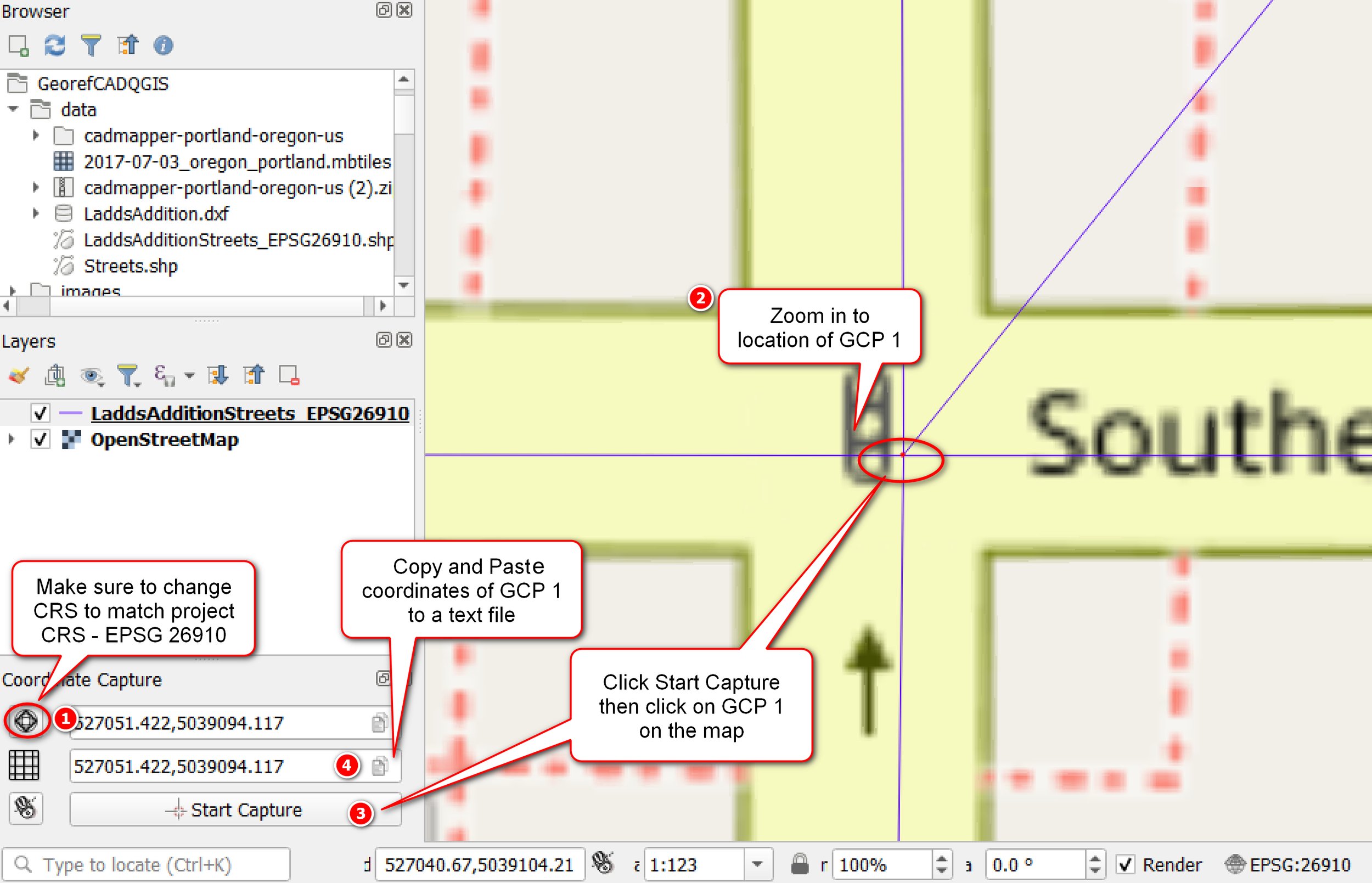
QGIS project with Streets/OSM for capturing coordinates for GCPs
Here is the XY coordinate pairs for the 4 GCPs in a text file. Select two GCPs that you want to use and save the text file as a world file (*.wld) with the same name as my DXF file (e.g. LaddsAddition.wld). You will use this world file in the next step to transform/georeference the DXF — the transformation (affine method) uses only 2 GCPs - hence why you only have two points in the wld file.
Option 1: Georeference DXF using world file
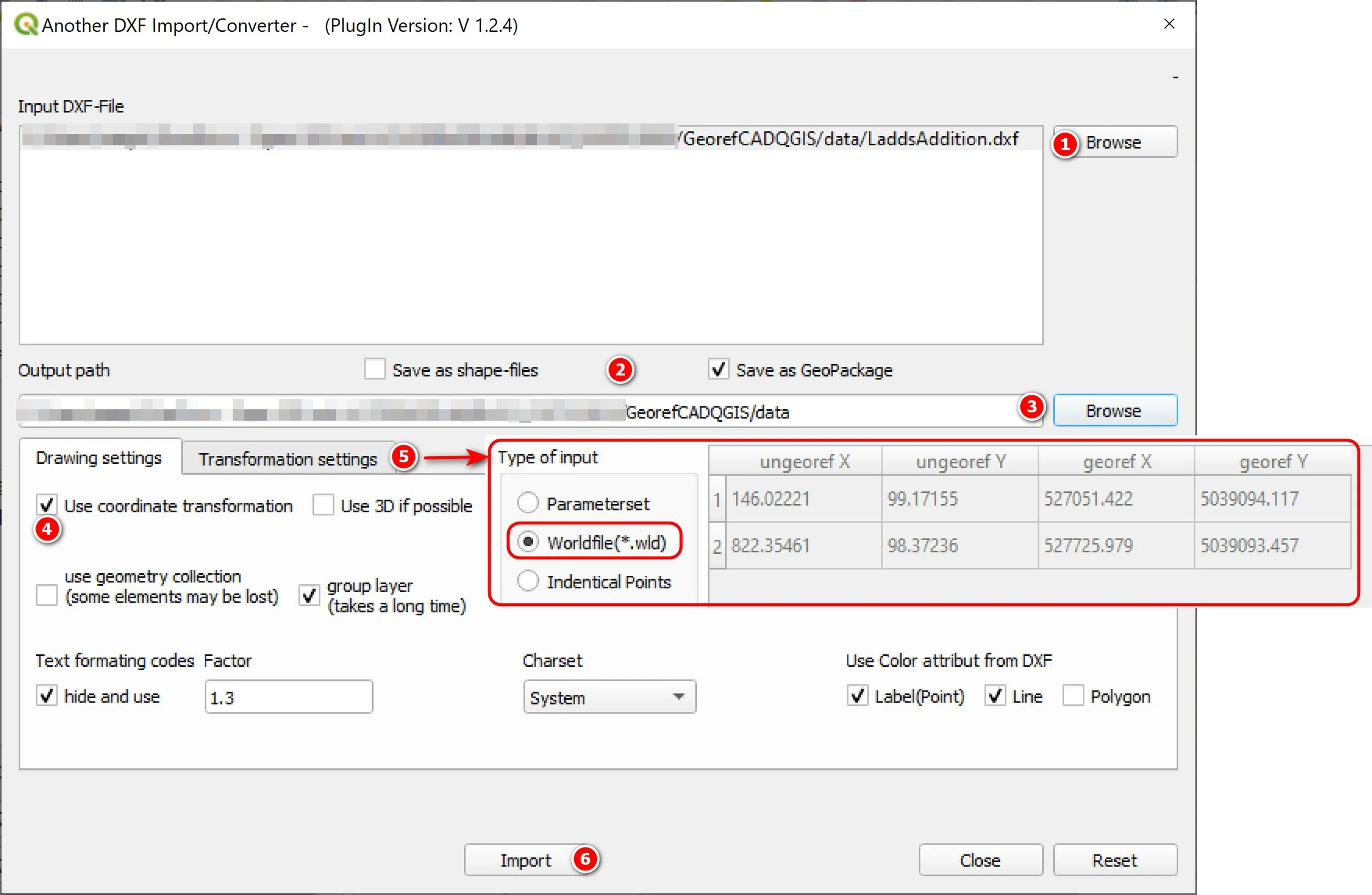
For this option, use Another DXF Importer plugin to transform the DXF using the world file you created in the above step. I find this option easier. Go to Vector menu >> DXF Import/Convert >> Import or Convert.
In the DXF Import/Converter window:
Browse to your DXF and select it as the input file
Choose if you want the output file as a shapefile or a Geopackage
Select output path location
Check the option to Use Coordinate Transformation
Make sure Worldfile (.wld) is selected and that it is using the correct file. The tool should pick up the corresponding wld file to the DXF file (if you named the *.wld file with the same file name as the DXF).
Click Import and wait for it to export
Once it finishes exporting, the layers will be automatically added to your TOC.
Note: you may get some warnings, such as “CRS was undefined: defaulting to CRS” and other warnings in the Processing Log tab — this is ok and can be disregarded.
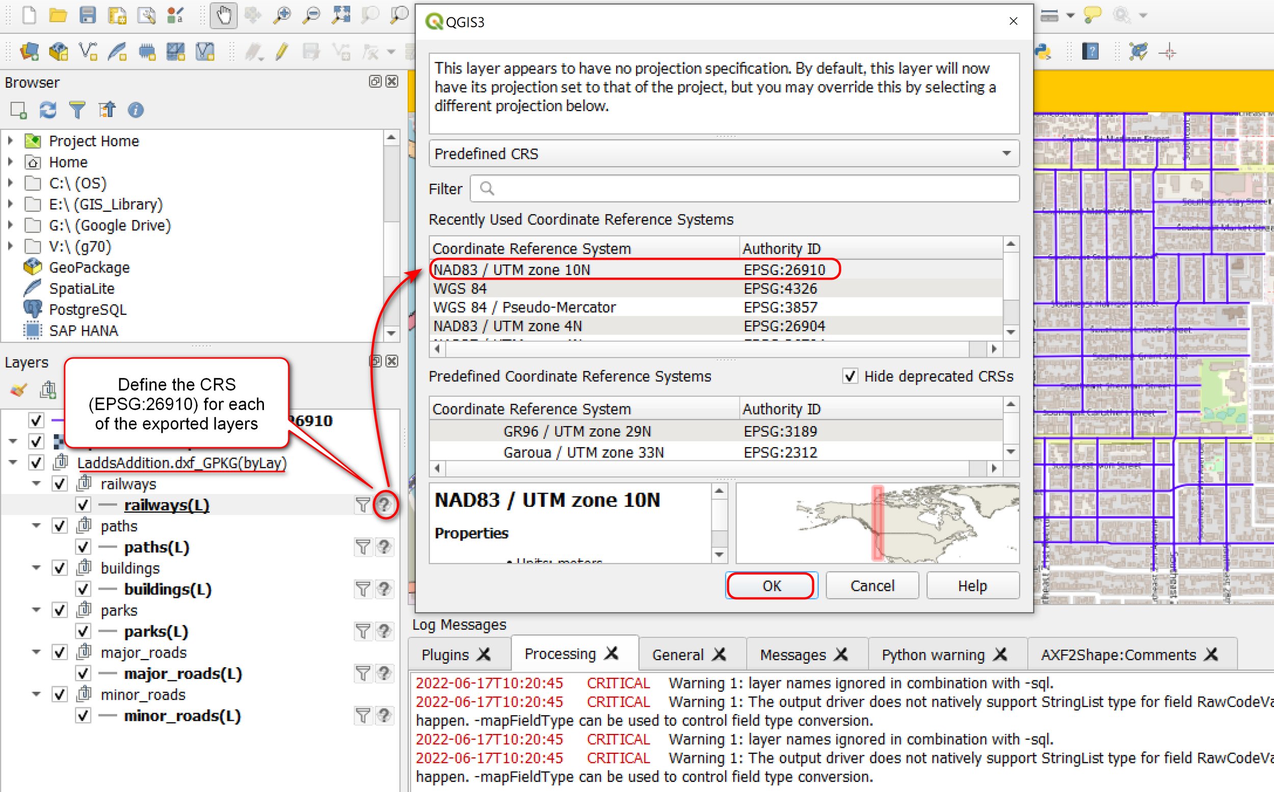
Define the CRS for Exported Layers
You’ll need to define the CRS of the exported layers then save your QGIS project.
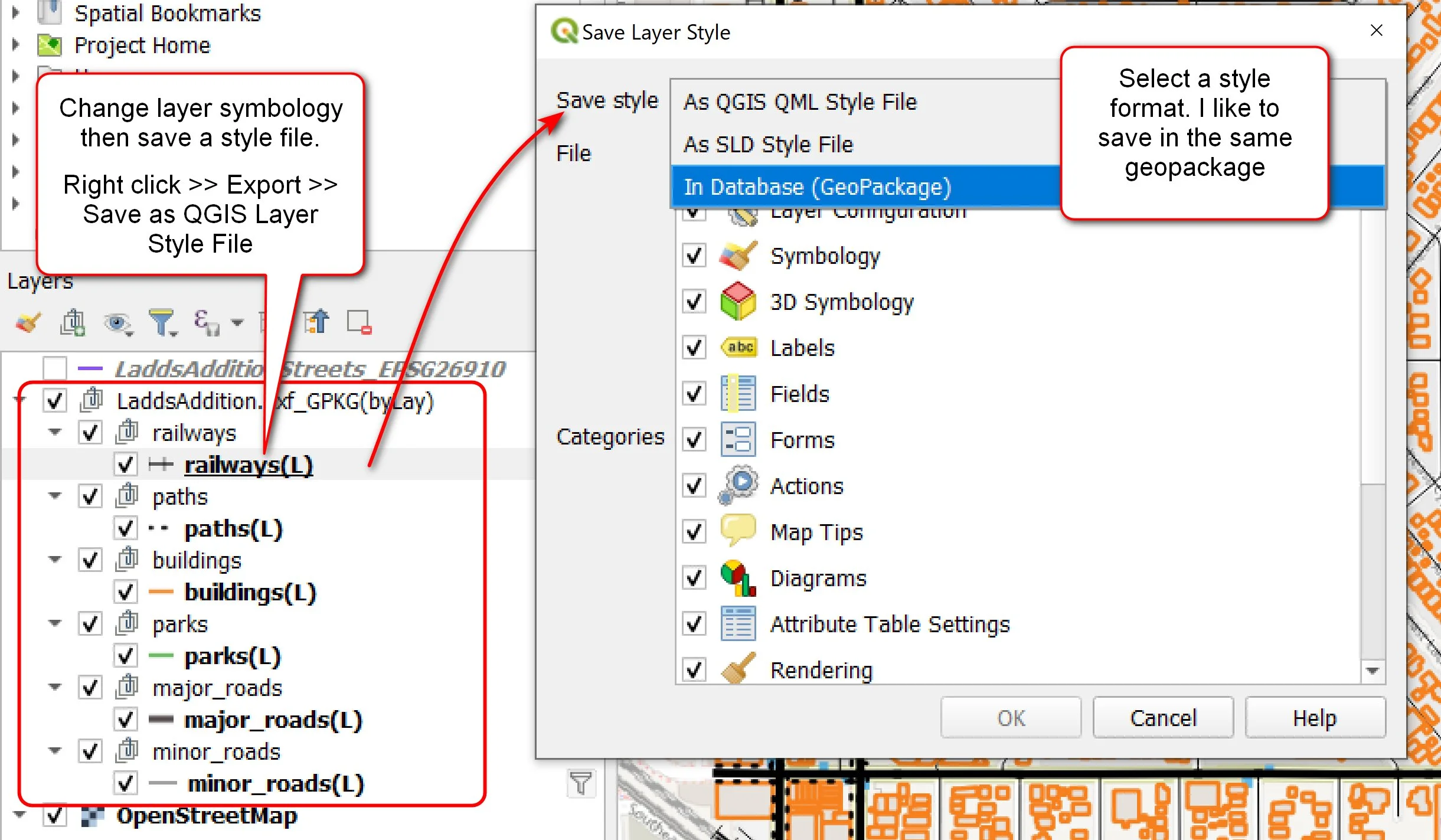
Change Layer Symbology and Save as Style file - Optional
After you define the CRS for each of the layers, you can change the layer symbology and then save it as a QGIS style file. See my example below.
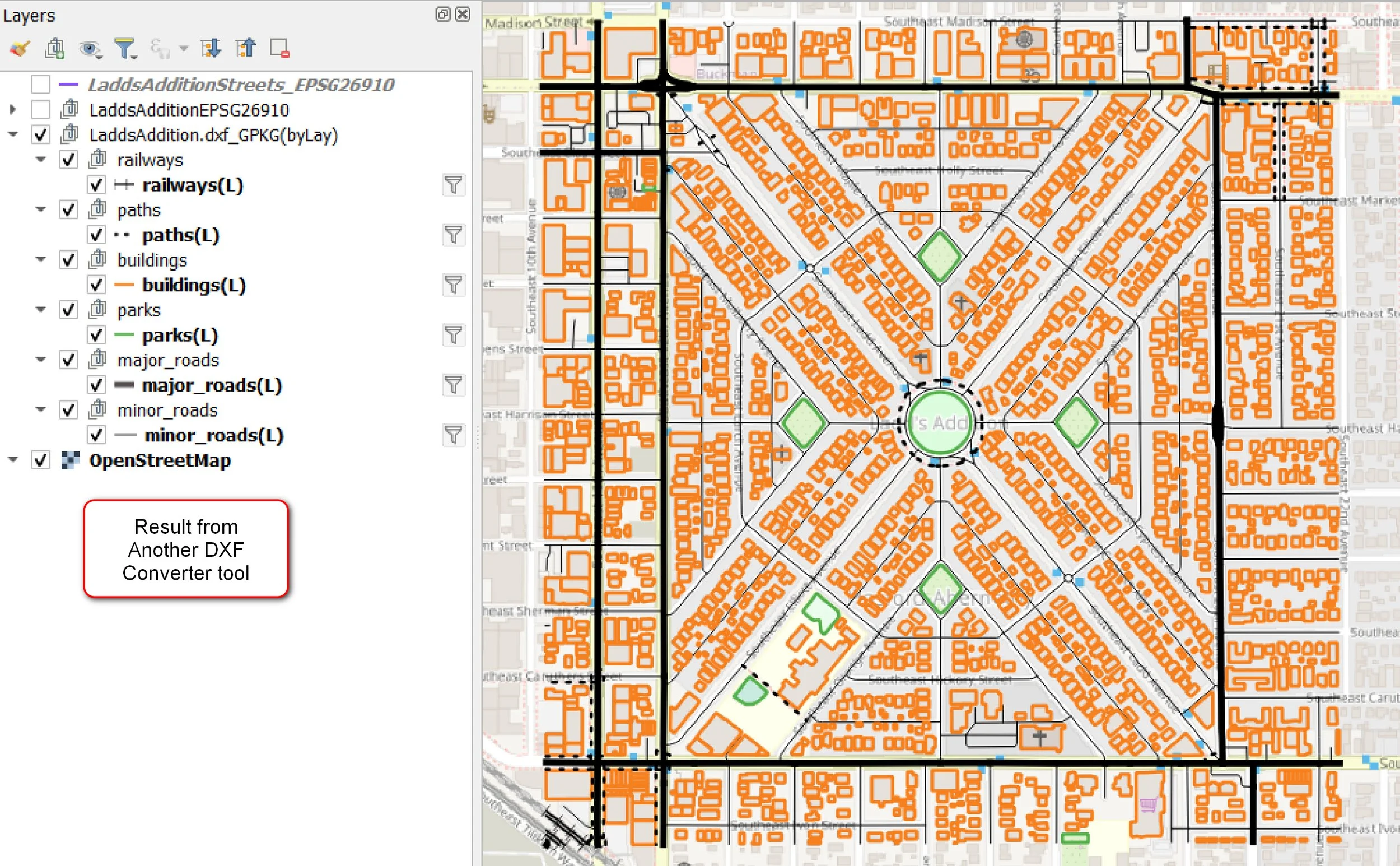
Here is my result from using the DXF Converter tool. I changed the symbology for the layers.
Option 2: GDAL ogr2ogr Vector Convert
If option 1 did not give you a good transformation (since it only uses 2 points) and you want to try using all 4 GCPs (or more) to georeference the DXF then you can use the GDAL org2org Vector Convert option. See documentation for more info on usage of the ogr2ogr command.
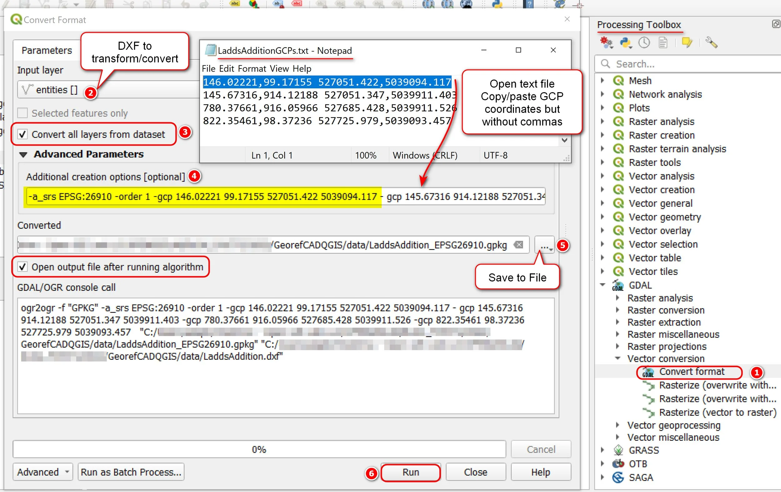
In the Processing Toolbox panel >> GDAL >> Vector Conversion >> Convert Format.
Double click Convert Format to open the window.
In the Convert Format window: Select your input DXF (if you added to the TOC then it should be auto filled)
Check the box to Convert all layers from dataset
Additional creation options:
Important: must specify a source SRS/CRS with -a_srs EPSG:xxxx option. I used the EPSG that I want to transform my DXF to (EPSG:26910). I tried specifying it as EPSGS:4326 as well in testing and it still converted fine. When I ran the process without the -a srs option the transformation didn’t work.
Specify transformation type -order 1. If you have >= 6 GCPs then transformation defaults to order 2 unless you specifically specify it as order 1. Type: order 1 = linear or affine, order 2 = second order polynomial. See ogr2ogr command usage
use -gcp option to include your GCPs for the transformation.
-gcp<ungeoref_x1>
-a_srs EPSG:26910 -order 1 -gcp 146.02221 99.17155 527051.422 5039094.117 -gcp 145.67316 914.12188 527051.347 5039911.403 -gcp 780.37661 916.05966 527685.428 5039911.526 -gcp 822.35461 98.37236 527725.979 5039093.457
5. Save to File: save the output file as a geopackage, shapefile or whatever format you want
6. Run it (hopefully everything works with no errors).
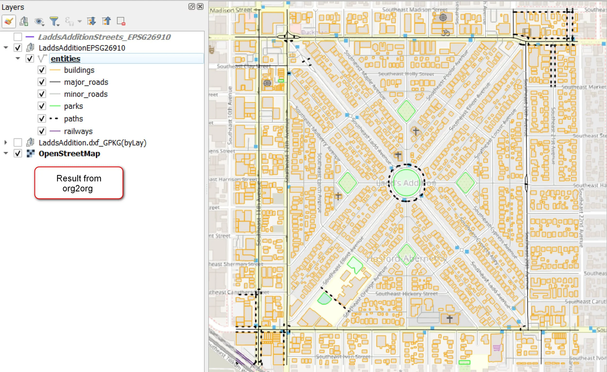
If all goes well, the output file should now be added to the TOC. Here is what my exported geopackage layers look like - I classified the layers and changed the symbology.
That’s it! This is the workflow I use to georeference CAD files that are not in a real world coordinate system. I hope you find this useful and that it will work for you.
And lastly, a shameless self promotion — I am now working as an independent consultant in Portland, OR. If you would like me to do some customized training or collaborate on one, please let me know. I’m also looking for jobs (full time or part time remote work, can do hybrid or onsite if in Portland) - if you know of any openings, please let me know.
Thanks for reading. Until next time :)